
Kia Carens: Smart Parking Assist System (SPAS) / Smart Parking Assist System Unit Components and components location
Kia Carens RP (2013-2018) Service Manual / Body Electrical System / Smart Parking Assist System (SPAS) / Smart Parking Assist System Unit Components and components location
| Component |
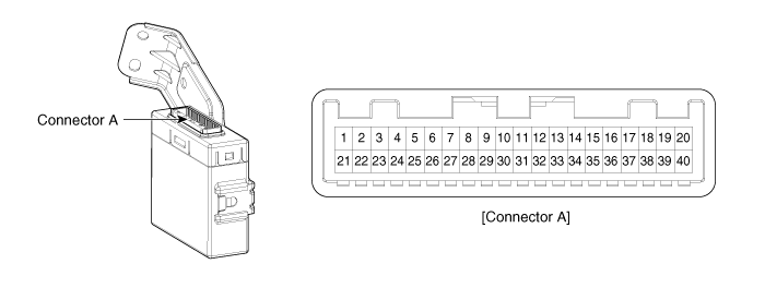
Connector Pin Information
|
No. |
Description |
No. |
Description |
|
1 |
- |
21 |
Ground |
|
2 |
- |
22 |
CAN H1 |
|
3 |
- |
23 |
CAN L1 |
|
4 |
- |
24 |
- |
|
5 |
- |
25 |
PAS switch indicator 2 |
|
6 |
PAS switch 2 |
26 |
SPAS switch indicator 1 |
|
7 |
SPAS switch 1 |
27 |
- |
|
8 |
- |
28 |
- |
|
9 |
- |
29 |
- |
|
10 |
- |
30 |
- |
|
11 |
Signal - Front side left sensor |
31 |
Signal - Front side right sensor |
|
12 |
-
|
32 |
- |
|
13 |
- |
33 |
- |
|
14 |
Front sensor ground |
34 |
Rear sensor ground |
|
15 |
Signal - Front outer right senosr |
35 |
Signal - Rear outer left sensor |
|
16 |
Signal - Front inner right senosr |
36 |
Signal - Rear inner left sensor |
|
17 |
Signal - Front inner left senosr |
37 |
Signal - Rear inner right sensor |
|
18 |
Signal - Front outer left senosr |
38 |
Signal - Rear outer right sensor |
|
19 |
Front sensor power |
39 |
Rear sensor power |
|
20 |
-
|
40 |
IGN |
 Description and operation
Description
Overview of the System Environment
The SPAS (Smart Parking Assist System) is part of a customer system providing
the PAS and the SPAS functionality to the driver.
...
 Smart Parking Assist System Unit Repair procedures
Removal
•
When prying with a flat-tip screwdriver, wrap it with protective
tap ...
Other information:
Kia Carens RP (2013-2018) Service Manual: Shift Cable Components and components location
Components 1. Shift lever knob 2. Shift lever assembly 3. Shift cable assembly 4. Retainer ...
Kia Carens RP (2013-2018) Service Manual: Instrument Cluster Repair procedures
Removal 1. Disconnect the negative (-) battery terminal. 2. Remove the cluster fascia panel. (Refer to Body - "Cluster Fascia Panel") 3. Remove the cluster (A) after removing 2 screws. ...
Copyright © www.kicaman.com 2015-2026
