Kia Carens: Smart Key System / Smart Key Unit Repair procedures
Kia Carens RP (2013-2018) Service Manual / Body Electrical System / Smart Key System / Smart Key Unit Repair procedures
| Removal |
Smart Key Unit
| 1. |
Disconnect the negative (-) battery terminal.
|
| 2. |
Remove the floor console upper cover.
(Refer to Body - "Floor Console Assembly")
|
| 3. |
Remove the audio unit/AVN head unit.
(Refer to Audio - "Audio Unit")
(Refer to AVN System - "AVN Head Unit")
|
| 4. |
Remove the smart key unit. (in the order as below)
|
RF Receiver
| 1. |
Disconnect the negative (-) battery terminal.
|
| 2. |
Remove the glove box housing.
(Refer toe Body - "Glove Box Housing")
|
| 3. |
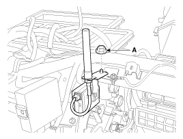
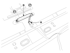
Loosen the mounting nut (A) from RF receiver.
|
| 4. |
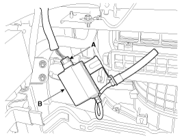
Remove the RF receiver (B) after disconnecting the connector (A).
|
Interior 1 Antenna
| 1. |
Disconnect the negative (-) battery terminal.
|
| 2. |
Remove the floor console upper cover.
(Refer to Body - "Floor Console Assembly")
|
| 3. |
Remove the heate and A/C control unit.
(Refer to Heating,Ventilation And Air Conditioning - "Heater & A/C Control
Unit (Manual)")
(Refer to Heating,Ventilation And Air Conditioning - "Heater & A/C Control
Unit (DATC)")
|
| 4. |
Remove the audio unit/AVN head unit.
(Refer to Audio - "Audio Unit")
(Refer to AVN System - "AVN Head Unit")
|
| 5. |
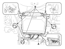
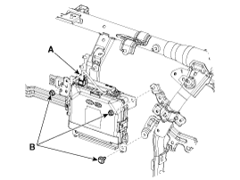
Disconnect the connectors (A) from the smart key unit and then loosen
the nuts (B).
[LHD]
[RHD]
|
| 6. |
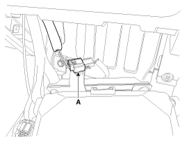
Disconnect the interior antenna connector (A).
|
| 7. |
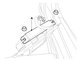
Remove the interior antenna (A) after loosening the nuts.
|
Interior 2 Antenna
| 1. |
Disconnect the negative (-) battery terminal.
|
| 2. |
Remove the rear console cover.
(Refer to Body - "Rear Console Cover")
|
| 3. |
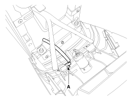
Disconnect the connector (A) from the interior 2 antenna.
|
| 4. |
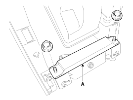
Remove the interior 2 antenna (A) after loosening the mounting nuts.
|
Interior 3 Antenna
| 1. |
Disconnect the negative (-) battery terminal.
|
| 2. |
Remove the third row seat assembly.
(Refer to Body - "Rear Seat Assembly")
|
| 3. |
Disconnect the connector (A) from the interior 3 antenna.
|
| 4. |
Remove the interior 3 antenna (B) after loosening the mounting nuts.
|
External Bumper Antenna
| 1. |
Disconnect the negative (-) battery terminal.
|
| 2. |
Remove the rear bumper cover.
(Refer to Body - "Rear Bumper Cover")
|
| 3. |
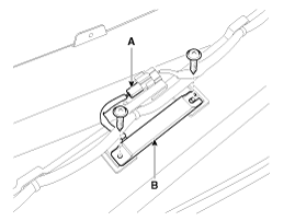
Disconnect the connector (A) from the bumper antenna.
|
| 4. |
Remove the bumper antenna (B) after loosening the mounting screws.
|
Buzzer
| 1. |
Disconnect the negative (-) battery terminal.
|
| 2. |
Remove the front left wheel guide.
|
| 3. |
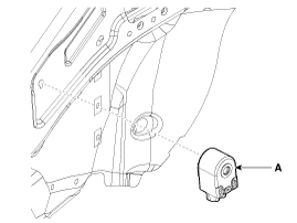
Disconnect the connectors, then remove the buzzer (A).
|
Door Outside Handle
| 1. |
Disconnect the negative (-) battery terminal.
|
| 2. |
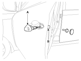
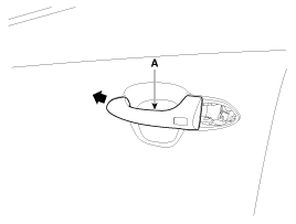
Remove the door outside handle cover (A) after seperating the plug hole
(B) from the door and loosening the mounting bolt.
|
| 3. |
Remove the outside handle (A) by sliding it rearward.
|
| 4. |
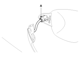
Disconnect the door outside handle connector (A).
|
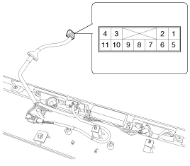
Tailgate Open Switch
| 1. |
Disconnect the negative (-) battery terminal.
|
| 2. |
Remove the tailgate trim.
(Refer to Body - "Tailgate Trim")
|
| 3. |
Remove the tailgate back panel.
(Refer to Body - "Tailgate Back Panel")
|
| 4. |
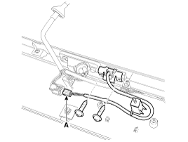
Disconnect the connector (A) from the back view camera.
|
| 5. |
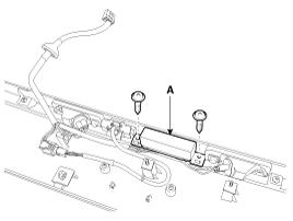
Remove the tailgate open switch (A) after loosening the mounting screws.
|
| Inspection |
Smart Key Unit
Refer to Smart Key System - "Smart Key Diagnostic"
Smart Key Switch
Refer to Smart Key System - "Smart Key Diagnostic"
Antenna
Refer to Smart Key System - "Smart Key Diagnostic"
Tailgate Switch
| 1. |
Check for continuity between the tailgate latch terminals.
|
| 2. |
If continuity is not specified, inspect the switch
|
| Installation |
Smart Key Unit
| 1. |
Install the interior 1 antenna on the smart key unit.
|
| 2. |
Connect the connector and then install the smart key unit.
|
| 3. |
Install the audio head unit or AVN head unit, heater & A/C control unit
and floor console upper cover.
|
| 4. |
Install the negative (-) battery terminal and check the smart key system.
|
RF Receiver
| 1. |
Install the RF receiver.
|
| 2. |
Install the RF receiver mounting nut and connect the connector.
|
| 3. |
Install the glove box housing.
|
| 4. |
Install the negative (-) battery terminal and check the smart key system.
|
Interior 1 Antenna
| 1. |
Install the interior 1 antenna on the smart key unit.
|
| 2. |
Connect the connector and then install the smart key unit.
|
| 3. |
Install the audio head unit or AVN head unit, heater & A/C control unit
and floor console upper cover.
|
| 4. |
Install the negative (-) battery terminal and check the smart key system.
|
Interior 2 Antenna
| 1. |
Install the interior 2 antenna.
|
| 2. |
Install the rear console cover.
|
| 3. |
Install the negative (-) battery terminal and check the smart key system.
|
Interior 3 Antenna
| 1. |
Install the interior 3 antenna.
|
| 2. |
Install the floor mat and second / third row seat assembly.
|
| 3. |
Install the negative (-) battery terminal and check the smart key system.
|
Exterior Bumper Antenna
| 1. |
Install the exterior bumper antenna.
|
| 2. |
Install the rear bumper cover.
|
| 3. |
Install the negative (-) battery terminal and check the smart key system.
|
Buzzer
| 1. |
Install the buzzer.
|
| 2. |
Install the front left wheel guide.
|
| 3. |
Install the negative (-) battery terminal and check the smart key system.
|
Door Outside Handle
| 1. |
Install the outside handle.
|
| 2. |
Install the door trim.
|
| 3. |
Install the negative (-) battery terminal and check the smart key system.
|
Tailgate Open Switch
| 1. |
Install the tailgate switch.
|
| 2. |
Install the tailgate garnish.
|
| 3. |
Install the tailgate trim.
|
| 4. |
Install the negative (-) battery terminal and check the smart key system.
|
 Smart Key Unit Schematic diagrams
Circuit Diagram
...
 Smart Key Diagnostic Repair procedures
Inspection
Self Diagnosis With GDS
Smart key system defects can be quickly diagnosed with the GDS. GDS operates
actuator quickly to monitor, input/output value and self diagnosi ...
Other information:
Kia Carens RP (2013-2018) Owners Manual: Lap belt
To fasten your seat belt: To fasten a 2-point static type belt, insert the metal tab (1) into the locking buckle (2). There will be an audible "click" when the tab locks into the buckle. Check to make sure the belt is properly locked and that the belt is not twisted. With a 2-point static type s ...
Kia Carens RP (2013-2018) Service Manual: UIP(Ultrasonic Intrusion Protection) Sensor Specifications
Specifications UIP sensor Item Specification Normal operating voltage DC 12V Operating voltage range DC 9V ~ 16V Operating temperature -40°C (-40°F) ~ 85°C (185° ...
Copyright © www.kicaman.com 2015-2026


