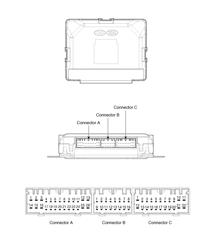
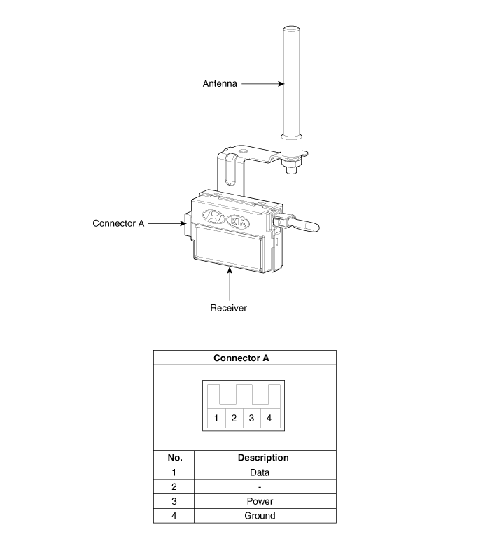
Kia Carens: Smart Key System / Smart Key Unit Components and components location
Kia Carens RP (2013-2018) Service Manual / Body Electrical System / Smart Key System / Smart Key Unit Components and components location
| Components (1) |

Connector Pin Information
|
No. |
Connector A |
Connector B |
Connector C |
|
1 |
V_BAT load |
C_CAN Low |
SSB illumination ground |
|
2 |
ESCL ground |
C_CAN High |
- |
|
3 |
Power ground1 |
- |
SSB LED OFF |
|
4 |
IGN1 |
- |
Interior antenna #2 power |
|
5 |
IGN1 relay |
Brake switch |
Interior antenna #1 power |
|
6 |
ACC |
Immobilizer antenna power |
- |
|
7 |
IGN2 |
ESCL enable |
- |
|
8 |
SSB switch2 |
Wheel speed |
Interior antenna #3 power |
|
9 |
- |
Driver toggle button |
Bumper antenna power |
|
10 |
RF COM |
ESCL unlock |
Assistant side antenna power |
|
11 |
ESCL COM |
External buzzer |
Driver side antenna power |
|
12 |
B_CAN High |
P position/ Clutch switch |
SSB LED IGN |
|
13 |
B_CAN Low |
Start feedback |
SSB illumination power |
|
14 |
V_BAT CPU |
Immobilizer antenna ground |
- |
|
15 |
ESCL battery |
- |
Interior antenna #2 ground |
|
16 |
Power ground2 |
SSB LED ACC |
Interior antenna #1 ground |
|
17 |
Starter relay |
|
- |
|
18 |
IGN2 relay |
- |
|
|
19 |
ACC relay |
Interior antenna #3 power |
|
|
20 |
- |
Bumper antenna ground |
|
|
21 |
- |
Assistant side antenna ground |
|
|
22 |
- |
Driver side antenna ground |
|
|
23 |
RPM |
|
|
|
24 |
EMS COM |
||
|
25 |
SSB switch1 |
||
|
26 |
Assistant toggle button |
| Components (2) |

 Smart Key Repair procedures
Smart Key
Smart Key Code Saving
1.
Connect the DLC cable of GDS to the data link connector (16 pins) in
driver side crash pad lower panel, turn the power on G ...
 Smart Key Unit Schematic diagrams
Circuit Diagram
...
Other information:
Kia Carens RP (2013-2018) Owners Manual: Trip A/B (for Type A cluster)
Tripmeter (1) The tripmeter is the total driving distance since the last tripmeter reset. - Distance range: 0.0 ~ 9999.9 km or mi. To reset the tripmeter, press the RESET button on the steering wheel for more than 1 second when the tripmeter is displayed. Average Vehicle Speed (2) The av ...
Kia Carens RP (2013-2018) Owners Manual: Changing a tire with TPMS
If you have a flat tire, the Low Tire Pressure telltale will come on. We recommend that the system be checked by an authorized Kia dealer. CAUTION We recommend that you use the sealant approved by Kia. The sealant on the tire pressure sensor and wheel shall be eliminated when you replace the tire ...
Copyright © www.kicaman.com 2015-2026

