Kia Carens: Front Axle Assembly / Front Hub / Knuckle / Repair procedures
Kia Carens RP (2013-2018) Service Manual / Driveshaft and axle / Front Axle Assembly / Front Hub / Knuckle / Repair procedures
| Replacement |
| 1. |
Loosen the wheel nuts slightly.
Raise the vehicle, and make sure it is securely supported.
|
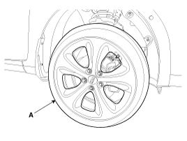
| 2. |
Remove the front wheel and tire (A) from front hub .
|

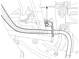
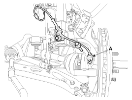
| 3. |
Remove the brake hose mounting bracket bolt (A).
|
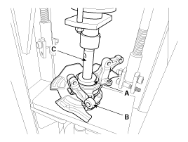
| 4. |
Loosen the guide rod bolt (B) and pivot the caliper (A) up out of the
way.
|

| 5. |
Remove the pad shim (D), pad retainers (C) and brake pads (B) in the
caliper carrier (A).
|
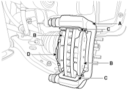
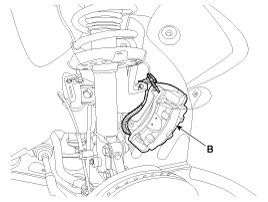
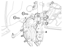
| 6. |
Remove the brake caliper mounting bolts (A), and then place the brake
caliper assembly (B) with wire.
|
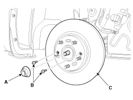
| 7. |
Loosen the coking nut (A) and screw (B) then remove the front brake
disc (C).
|
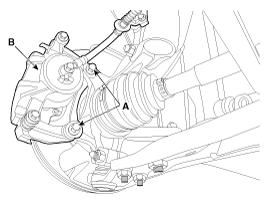
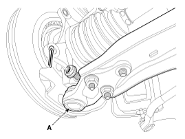
| 8. |
Remove the tie rod end ball joint (A) from the knuckle.
|
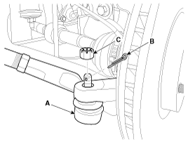
| 9. |
Loosen the mount bolt and then remove the wheel speed sensor (A) from
knuckle.
|
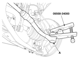
| 10. |
Remove the lower arm (A) from the knuckle.
|
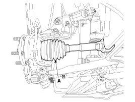
| 11. |
Disconnect the driveshaft (A) from the front hub assembly.
|
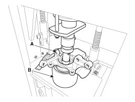
| 12. |
Loosen the strut mounting bolts and then remove the knuckle assembly
(A).
|
| Disassembly |
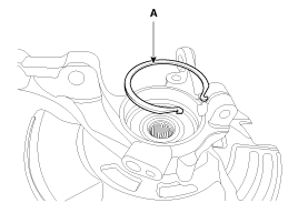
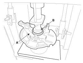
| 1. |
Remove the snap ring (A).
|
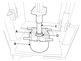
| 2. |
Remove the hub assembly from the knuckle assembly.
|
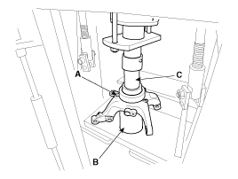
| 3. |
Remove the hub bearing inner race from the hub assembly.
|
| 4. |
Remove the hub bearing outer race from the knuckle assembly.
|
| 5. |
Replace hub bearing with a new one.
|
| Reassembly |
| 1. |
Install the hub bearing to the knuckle assembly.
|
| 2. |
Install the hub assembly to the knuckle assembly.
|
| 3. |
Install the snap ring (A).
|
| Inspection |
| 1. |
Check the hub for cracks and the splines for wear.
|
| 2. |
Check the brake disc for scoring and damage.
|
| 3. |
Check the knuckle for cracks.
|
| 4. |
Check the bearing for cracks or damage.
|
| Installation |
| 1. |
Install in the reverse order of removal.
|

| 2. |
Check the front alignment.
(Refer to Suspension System - "Front Alignment")
|
 Components and components location
Components
1. Brake disc
2. Wheel hub assembly
3. Hub bolt
4. Dust cover
5. Knuckle
6. Hub bearing
7. Snap ring
...

Other information:
Kia Carens RP (2013-2018) Service Manual: Alternator Repair procedures
Removal 1. Disconnect the battery negative terminal. 2. Loosen the mounting bolts (A) and then, turn the adjusting bolt (B) clockwise to loosen tension. 3. Remove the drive belt (A). ...
Kia Carens RP (2013-2018) Service Manual: Compressor Repair procedures
Removal 1. If the compressor is marginally operable, run the engine at idle speed, and let the air conditioning work for a few minutes, then shut the engine off. 2. Disconnect the negative (-) battery terminal. ...
Copyright © www.kicaman.com 2015-2026
