Kia Carens: Charging System / Battery Repair procedures
Kia Carens RP (2013-2018) Service Manual / Engine Electrical System / Charging System / Battery Repair procedures
| Adjustment |
Battery Charging
In general, vehicle battery charging system has three forms.
| 1. |
Constant current charge: The battery voltage gradually rises by charging
with setting a constant current. If charging current and time are not
managed correctly, the battery is over-charged, therefore charging should
be stopped after confirming the completion of charging.
|
| 2. |
Constant voltage charge: The battery charge current is gradually reduced
by charging with setting a constant voltage.
|
| 3. |
Constant current-Constant voltage charge: Charging with constant current
and voltage to protect the battery damage
|

[AGM Battery Charging]
AGM battery should be charged with constant voltage or constant current-constant
voltage in order to minimize performance degradation due to the charging.
If charging the battery with constant current, overcharging may occur. It can
cause damage to the internal battery and will give an adverse effect on battery
life.
Do not charge with more than 14.8V or quick charge mode.
|

[Constant Voltage Charge Conditions]
|
Charging voltage / time: 14.7V [68°F ~ 86°F (20°C ~ 30°C)] / approximately
24 hours
The minimum charge voltage: 14.4V [68°F ~ 86°F (20°C ~ 30°C)]
The maximum charging voltage: 14.8V [68°F ~ 86°F (20°C ~ 30°C)]
|
Battery temperature should be maintained at about 68°F ~ 86°F (20°C
~ 30°C) during charging of the battery.
|

If the battery is charged directly at the battery terminals on vehicles
with battery sensor, misinterpretations of battery condition and under
certain circumstances also unwanted Check Control messages or fault
memory entire can occur.
After recharging finished, let the battery stand for over 10 hours with
normal temperature for battery stabilization.
|
Electrolyte Level Inspection (MF Openable Battery only)
| 1. |
Check that the electrolyte level lies between the “UPPER” and the
“LOWER” lines.
|
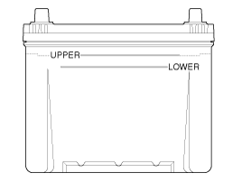
| 2. |
If the electrolyte level is below the "LOWER" line, add water until
the level of electrolyte comes up to the "UPPER" level.
|
| Removal |
| 1. |
Turn the ignition switch OFF and disconnect the battery negative (-)
cable.
|
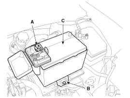
| 2. |
Disconnect the positive (+) terminals (A) from the battery.
|
| 3. |
Remove the battery insulation pad.
|
| 4. |
Remove the battery mounting bracket (B) by loosening the mounting bolt
and then remove the battery (C).
|
| 5. |
Remove the ECM. (Refer to Engine Control/Fuel System - “Engine Control
Module (ECM)”)
|
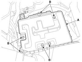
| 6. |
Remove the battery tray (A) after removing the bolts (B).
|
| Installation |
| 1. |
Install in the reverse order of removal.
|

| Vehicle parasitic current inspection |
| 1. |
Turn the all electric devices OFF, and then turn the ignition switch
OFF.
|
| 2. |
Close all doors except the engine hood, and then lock all doors.
|
| 3. |
Wait a few minutes until the vehicle’s electrical systems go to sleep
mode.
|
| 4. |
Connect an ammeter in series between the battery (-) terminal and the
ground cable, and then disconnect the clamp from the battery (-) terminal
slowly.
|
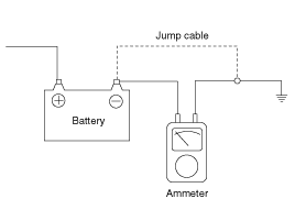
| 5. |
Read the current value of the ammeter.
|
| Cleaning |
| 1. |
Make sure the ignition switch and all accessories are in the OFF position.
|
| 2. |
Disconnect the battery cables (negative first).
|
| 3. |
Remove the battery from the vehicle.
|
| 4. |
Inspect the battery tray for damage caused by the loss of electrolyte.
If acid damage is present, it will be necessary to clean the area with
a solution of clean warm water and baking soda. Scrub the area with
a stiff brush and wipe off with a cloth moistened with baking soda and
water.
|
| 5. |
Clean the top of the battery with the same solution as described above.
|
| 6. |
Inspect the battery case and cover for cracks. If cracks are present,
the battery must be replaced.
|
| 7. |
Clean the battery posts with a suitable battery post tool.
|
| 8. |
Clean the inside surface of the terminal clamps with a suitable battery
cleaning tool. Replace damaged or frayed cables and broken terminal
clamps.
|
| 9. |
Install the battery in the vehicle.
|
| 10. |
Connect the cable terminals to the battery post, making sure tops of
the terminals are flush with the tops of the posts .
|
| 11. |
Tighten the terminal nuts securely.
|
| 12. |
Coat all connections with light mineral grease after tightening.
|
 Battery Components and components location
Components
1. Battery insulation pad
2. Battery
3. Battery tray
4. Battery mounting bracket
...
 Battery Troubleshooting
Troubleshooting
...
Other information:
Kia Carens RP (2013-2018) Service Manual: Injector Repair procedures
Inspection 1. Turn the ignition switch OFF. 2. Disconnect the injector connector. 3. Measure resistance between the injector terminals 1 and 2. 4. Check that the resistance i ...
Kia Carens RP (2013-2018) Service Manual: Audio Unit Components and components location
Components Connector Pin Information No. Connector A Connector B 1 Rear left speaker (+) - 2 Front left speaker (+) - 3 Front ...
Copyright © www.kicaman.com 2015-2026
