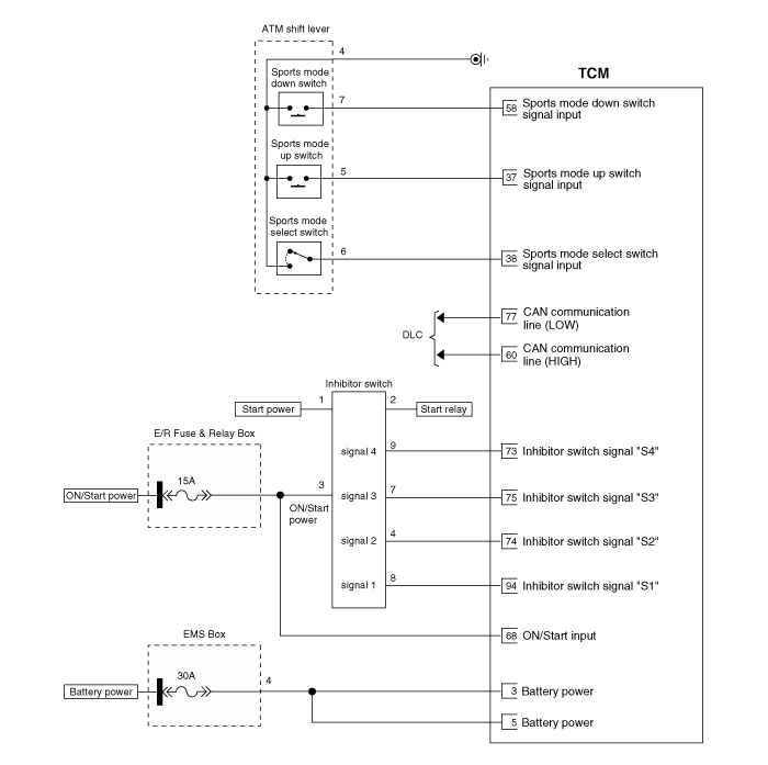
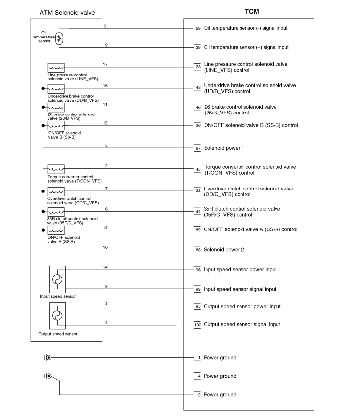
Kia Carens: Automatic Transaxle Control System / Transaxle Control Module (TCM) Schematic diagrams
Kia Carens RP (2013-2018) Service Manual / Automatic Transaxle System / Automatic Transaxle Control System / Transaxle Control Module (TCM) Schematic diagrams
| TCM connector and terminal function |

| TCM Terminal Function |
Connector [A]
|
Pin |
Description |
Pin |
Description |
|
22 |
Overdrive clutch control solenoid valve (OD/C_VFS) |
73 |
Inhibitor switch signal "S4" |
|
23 |
Pressure control solenoid (VFS-LINE) |
74 |
Inhibitor switch signal "S2" |
|
26 |
ON/OFF solenoid valve B (SS-B) |
75 |
Inhibitor switch signal "S3" |
|
37 |
Sports mode up switch |
87 |
Solenoid power 1 |
|
38 |
Sports mode select switch |
88 |
Solenoid power 2 |
|
39 |
Oil temperature sensor (+) |
89 |
ON/OFF solenoid valve A (SS-A) |
|
43 |
Underdrive brake control solenoid valve (UD/B_VFS) |
94 |
Inhibitor switch signal "S1" |
|
44 |
35R clutch control solenoid valve (35R/C_VFS) |
95 |
Output speed sensor power |
|
45 |
Torque converter control solenoid (T/CON_VFS) |
96 |
Input speed sensor power |
|
46 |
26 brake control solenoid valve (26/B_VFS) |
99 |
Input speed sensor signal |
|
58 |
Sports mode down switch |
100 |
Output speed sensor signal |
|
59 |
Oil temperature sensor (-) |
|
|
Connector [B]
|
Pin |
Description |
Pin |
Description |
|
1 |
GND (Power) |
5 |
VB (Battery voltage) |
|
2 |
GND (Power) |
60 |
CAN High |
|
3 |
VB (Battery voltage) |
68 |
IG.1 ( Ignition key) |
|
4 |
Ground (Power) |
77 |
CAN Low |
| TCM Terminal input/ output signal |
Connector [A]
|
Pin |
Description |
Condition |
Input/output value |
|
|
Type |
Level |
|||
|
22 |
Overdrive clutch control solenoid valve (OD/C_VFS) |
- |
Output |
0V/Battery voltage level |
|
9V < Battery voltage level < 16V |
||||
|
23 |
Line pressure control solenoid valve (LINE_VFS) |
- |
Output |
0V/Battery voltage level |
|
9V < Battery voltage level < 16V |
||||
|
26 |
ON/OFF solenoid valve B(SS-B) |
High |
Output |
0V/Battery voltage level |
|
Low |
9V < Battery voltage level < 16V |
|||
|
37 |
Sports mode up switch |
Up ON |
Input |
0V/Battery voltage level |
|
Other |
9V < Battery voltage level < 16V |
|||
|
38 |
Sports mode select switch |
Sport mode |
Input |
0V/Battery voltage level |
|
Other |
9V < Battery voltage level < 16V |
|||
|
39 |
Oil temperature sensor (+) |
ON |
Input |
0V/3.3V |
|
OFF |
||||
|
43 |
Underdrive brake control solenoid valve (UD/B_VFS) |
- |
Output |
0V/Battery voltage level |
|
9V < Battery voltage level < 16V |
||||
|
Power supply : V_SOL2 |
||||
|
44 |
35R clutch control solenoid valve (35R/C_VFS) |
- |
Output |
0V/Battery voltage level |
|
9V < Battery voltage level < 16V |
||||
|
45 |
Torque converter control solenoid valve (T/CON_VFS) |
- |
Output |
0V/Battery voltage level |
|
9V < Battery voltage level < 16V |
||||
|
46 |
26 brake control solenoid valve (26/B_VFS) |
- |
Output |
0V/Battery voltage level |
|
9V < Battery voltage level < 16V |
||||
|
Power supply : V_SOL2 |
||||
|
58 |
Sports mode down switch |
Down ON |
Input |
0V/Battery
voltage level |
|
Other |
9V < Battery voltage level < 16V |
|||
|
59 |
Oil temperature sensor (-) |
- |
Ground |
0V |
|
73 |
Inhibitor switch signal "S4" |
High |
Input |
0V/Battery voltage level |
|
Low |
9V < Battery voltage level < 16V |
|||
|
74 |
Inhibitor switch signal "S2" |
High |
Input |
0V/Battery voltage level |
|
Low |
9V < Battery voltage level < 16V |
|||
|
75 |
Inhibitor switch signal "S3" |
High |
Input |
0V/Battery voltage level |
|
Low |
9V < Battery voltage level < 16V |
|||
|
89 |
ON/OFF solenoid valve A (SS-A) |
High |
Output |
0V/Battery voltage level |
|
Low |
9V < Battery voltage level < 16V |
|||
|
94 |
Inhibitor switch signal "S1" |
High |
Input |
0V/Battery voltage level |
|
Low |
9V < Battery voltage level < 16V |
|||
|
95 |
Output speed sensor power |
ON |
Power |
0V/7.5V |
|
OFF |
||||
|
96 |
Input speed sensor power |
ON |
Power |
0V/7.5V |
|
OFF |
||||
|
99 |
Input speed sensor signal |
High |
Input |
0.7V/1.4V |
|
Low |
||||
|
100 |
Output speed sensor signal |
High |
Input |
0.7V/1.4V |
|
Low |
||||
| Circuit Diagram |


 Transaxle Control Module (TCM) Description and operation
Description
The module receives and processes signals from various sensors and implements
a wide range of transaxle controls to ensure optimal driving conditions for
the driver. ...
 Transaxle Control Module (TCM) Repair procedures
Inspection
1.
TCM ground circuit test : Measure the resistance between TCM and chassis
ground. (Inspect the terminal connected to the chassis ground with the
...
Other information:
Kia Carens RP (2013-2018) Service Manual: Fuel Pressure Control Valve Repair procedures
Inspection 1. Turn the ignition switch OFF and disconnect the battery negative (-) cable. 2. Disconnect the fuel pressure regulator valve connector. 3. Measure resistance between the fuel pressure reg ...
Kia Carens RP (2013-2018) Service Manual: Repair procedures
Replacement 1. Loosen the wheel nuts slightly. Raise the vehicle, and make sure it is securely supported. 2. Remove the front wheel and tire (A) from front hub . Tightening torque: 88.3 ...
Copyright © www.kicaman.com 2015-2026

