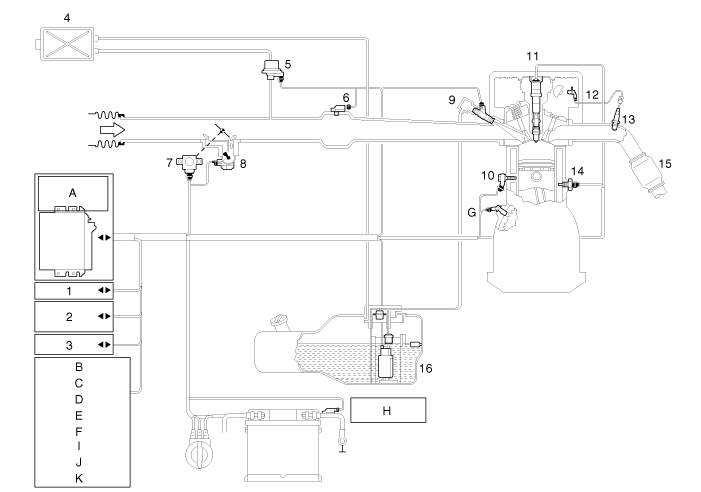
Kia Carens: ISG (Idle Stop & Go) System / Schematic diagrams
Kia Carens RP (2013-2018) Service Manual / Engine Control / Fuel System / ISG (Idle Stop & Go) System / Schematic diagrams
| Schematic Diagram |

| 1. CAN 2. MIL lamp 3. Immobilizer 4. Canister 5. Purge control solenoid valve 6. Manifold absolute pressure sensor 7. Throttle position sensor (ETC module included) 8. ETC motor 9. Injector 10. Knock sensor 11. Iginition coil 12. Camshaft position sensor 13. Heated oxygen sensor 14. Engine coolant temperature sensor |
15. Catalyst 16. Low pressure pump A. Engine control module (ECM) B. Clutch switch C. Neutral switch D. Brake booster vacuum pressure sensor E. Alternator control F. Start motor G. Crankshaft position sensor H. Battery sensor I. DC/DC converter J. Hood switch K. Door / Seat belt switch (Driver's) |
The ISG system is strongly networked with the power management. In the
event of battery replacement, disconnection of the battery terminal
or after changing the engine management system, the reference data regarding
the battery charge state and battery condition can be lost.
They are only available again a closed-circuit current measurement of
approximate 4 hours in which the vehicle may not be wakened. In this
time, the ISG system is inactive.
|
 Repair procedures
Inspection
1.
Remove the ISG switch from the switch assembly.
2.
Check the continuity between the switch 5 and 12 terminals as the ISG
...
Other information:
Kia Carens RP (2013-2018) Owners Manual: Weight of the trailer tongue
The tongue load of any trailer is an important weight to measure because it affects the total gross vehicle weight (GVW) of your vehicle. This weight includes the curb weight of the vehicle, any cargo you may carry in it, and the people who will be riding in the vehicle. And if you will tow a tr ...
Kia Carens RP (2013-2018) Service Manual: Head Lamps Components and components location
Component 1. Static bending lamp bulb 2. Head lamp high beam bulb 3. Head lamp low beam bulb 4. Dust cap (Low) 5. Turn signal lamp socket 6. Turn signal lamp bulb 7. Dust cap (High) 1. Static bending lamp bul ...
Copyright © www.kicaman.com 2015-2026


