Kia Carens: Clutch Release Fork and Clutch Release Bearing / Repair procedures
Kia Carens RP (2013-2018) Service Manual / Clutch System / Clutch Release Fork and Clutch Release Bearing / Repair procedures
| Removal |
| 1. |
Remove the transaxle assembly.
G 1.6 GDI (Refer to Manual Transaxle System - " Manual Transaxle")
G 2.0 GDI (Refer to Manual Transaxle System - " Manual Transaxle")
G 2.0 MPI (Refer to Manual Transaxle System - " Manual Transaxle")
D 1.7 LP (Refer to Manual Transaxle System - " Manual Transaxle")
|
| 2. |
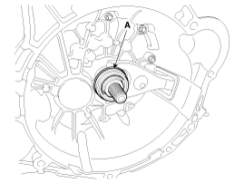
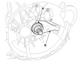
Remove the clutch release bearing (A).
|
| 3. |
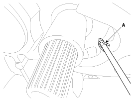
Pull the clip (A).
|
| 4. |
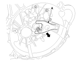
Remove the clutch release fork (A).
|
| 5. |
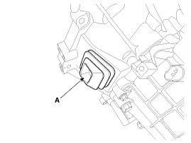
Remove the boot (A).
|
| Inspection |
| 1. |
Check for damage to boot.
|
| 2. |
Check for deformation to clutch release fork.
|
| 3. |
Check for deformation to clutch release bearing.
|
| Installation |
| 1. |
Install the boot (A).
|
| 2. |
Install the clip to the clutch release fork.
|
| 3. |
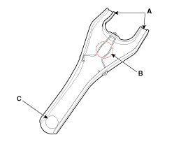
Apply to grease in location A, B and C.
|
| 4. |
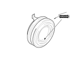
Apply the grease to the hole surface of the clutch release bearing all
around.
|
| 5. |
Install the clutch release fork (B), clutch release bearing (A).
|
| 6. |
Install the transaxle assembly.
G 1.6 GDI (Refer to Manual Transaxle System - " Manual Transaxle")
G 2.0 GDI (Refer to Manual Transaxle System - " Manual Transaxle")
G 2.0 MPI (Refer to Manual Transaxle System - " Manual Transaxle")
D 1.7 LP (Refer to Manual Transaxle System - " Manual Transaxle")
|
 Components and components location
Components
1. Clutch release fork
2. Clutch cover assembly
3. Clutch disk assembly
4. Clutch release bearing
...
Other information:
Kia Carens RP (2013-2018) Service Manual: Front Bumper Cover Components and components location
Component Location 1. Front bumper cover ...
Kia Carens RP (2013-2018) Owners Manual: Cool box
You can keep beverage cans or other items cool in the glove box. 1. Turn on the air conditioning. The temperature of the cool box will change according to the temperature of air conditioning. 2. Turn the knob to the open position. 3. When the cool box is not used, turn the knob to the close positi ...
Copyright © www.kicaman.com 2015-2026


