Kia Carens: Rear Seat / Rear Seat Frame Assembly Repair procedures
[Second row seat assembly]
| (Except Europe and Australia) |
| • |
Put on gloves to protect your hands.
|
|
| • |
When prying with a flat-tip screwdriver, wrap it with protective
tape, and apply protective tape around the related parts, to
prevent damage.
|
| • |
Use a plastic panel removal tool to remove interior trim pieces
to protect from marring the surface.
|
| • |
Take care not to bend or scratch the trim and panels.
|
|
| 1. |
Remove the rear seat back cover [LH].
(Refer to Rear Seat - "Rear Seat Back Cover")
|
| 2. |
Remove the rear seat cushion cover.
(Refer to Rear Seat - "Rear Seat Cushion Cover")
|
| 3. |
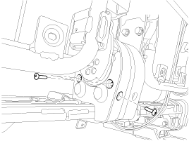
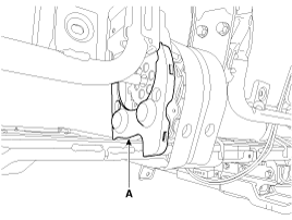
After loosening the mounting screws, then remove the rear seat cushion
inside inner cover (A).
|
| 4. |
Folding the rear seat back assembly[LH].
|
| 5. |
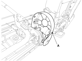
Remove the rear seat cushion inside outer cover (A).
|
| 6. |
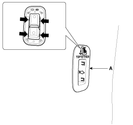
Remove the tether anchor garnish (A).
|
| 7. |
Remove the rear seat back board (A).
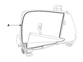
|
| 8. |
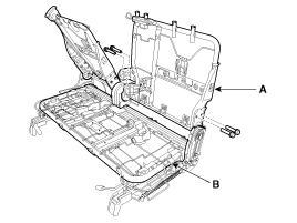
After loosening the mounting bolts, then disconnect the rear seat back
frame assembly (A) and rear seat cushion frame assembly (B).
|
Tightening torque :
44.1 ~ 53.9 N.m (4.5 ~ 5.5 kgf.m, 32.5 ~ 39.8 lb-ft)
|
|
| 9. |
Install in the reverse order of removal.
| •
|
Replace any damaged clips.
|
|
|
| • |
Put on gloves to protect your hands.
|
|
| • |
When prying with a flat-tip screwdriver, wrap it with protective
tape, and apply protective tape around the related parts, to
prevent damage.
|
| • |
Use a plastic panel removal tool to remove interior trim pieces
to protect from marring the surface.
|
| • |
Take care not to bend or scratch the trim and panels.
|
|
| 1. |
Remove the rear seat back cover [RH].
(Refer to Rear Seat - "Rear Seat Back Cover")
|
| 2. |
Remove the rear seat cushion cover.
(Refer to Rear Seat - "Rear Seat Cushion Cover")
|
| 3. |
Remove the tether anchor garnish (A).

|
| 4. |
Remove the rear seat back board (A).
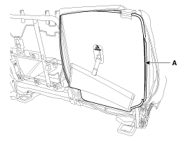
|
| 5. |
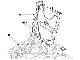
After loosening the mounting bolts, then disconnect the rear seat back
frame assembly (A) and rear seat cushion frame assembly (B).
|
Tightening torque :
44.1 ~ 53.9 N.m (4.5 ~ 5.5 kgf.m, 32.5 ~ 39.8 lb-ft)
|
|
| 6. |
Install in the reverse order of removal.
| •
|
Replace any damaged clips.
|
|
|
| (Except Europe and Australia) |
| • |
Put on gloves to protect your hands.
|
|
| • |
When prying with a flat-tip screwdriver, wrap it with protective
tape, and apply protective tape around the related parts, to
prevent damage.
|
| • |
Use a plastic panel removal tool to remove interior trim pieces
to protect from marring the surface.
|
| • |
Take care not to bend or scratch the trim and panels.
|
|
| 1. |
Remove the rear seat back cover [LH].
(Refer to Rear Seat - "Rear Seat Back Cover")
|
| 2. |
Remove the rear seat cushion cover [LH].
(Refer to Rear Seat - "Rear Seat Cushion Cover")
|
| 3. |
Remove the tether anchor garnish (A).
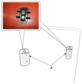
|
| 4. |
Remove the rear seat back board (A).
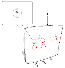
|
| 5. |
After loosening the mounting bolts, then disconnect the rear seat back
frame assembly (A) and rear seat cushion frame assembly (B).
|
Tightening torque :
44.1 ~ 53.9 N.m (4.5 ~ 5.5 kgf.m, 32.5 ~ 39.8 lb-ft)
|
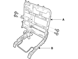
|
| 6. |
Install in the reverse order of removal.
| •
|
Replace any damaged clips.
|
|
|
| • |
Put on gloves to protect your hands.
|
|
| • |
When prying with a flat-tip screwdriver, wrap it with protective
tape, and apply protective tape around the related parts, to
prevent damage.
|
| • |
Use a plastic panel removal tool to remove interior trim pieces
to protect from marring the surface.
|
| • |
Take care not to bend or scratch the trim and panels.
|
|
| 1. |
Remove the rear seat back cover [RH].
(Refer to Rear Seat - "Rear Seat Back Cover")
|
| 2. |
Remove the rear seat cushion cover [RH].
(Refer to Rear Seat - "Rear Seat Cushion Cover")
|
| 3. |
Remove the tether anchor garnish (A).
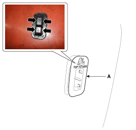
|
| 4. |
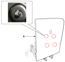
Remove the rear seat back board (A).
|
| 5. |
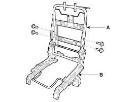
After loosening the mounting bolts, then disconnect the rear seat back
frame assembly (A) and rear seat cushion frame assembly (B).
|
Tightening torque :
44.1 ~ 53.9 N.m (4.5 ~ 5.5 kgf.m, 32.5 ~ 39.8 lb-ft)
|
|
| 6. |
Install in the reverse order of removal.
| •
|
Replace any damaged clips.
|
|
|
| (For Europe and Australia) |
| • |
Put on gloves to protect your hands.
|
|
| • |
When prying with a flat-tip screwdriver, wrap it with protective
tape, and apply protective tape around the related parts, to
prevent damage.
|
| • |
Use a plastic panel removal tool to remove interior trim pieces
to protect from marring the surface.
|
| • |
Take care not to bend or scratch the trim and panels.
|
|
| 1. |
Remove the rear seat back cover.
(Refer to Rear Seat - "Rear Seat Back Cover")
|
| 2. |
Remove the rear seat cushion cover.
(Refer to Rear Seat - "Rear Seat Cushion Cover")
|
| 3. |
Remove the tether anchor garnish (A).

|
| 4. |
Remove the rear seat back board (A).
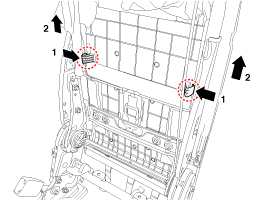
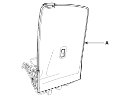
|
| 5. |
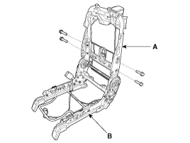
After loosening the mounting bolts, then disconnect the rear seat back
frame assembly (A) and rear seat cushion frame assembly (B).
|
Tightening torque :
44.1 ~ 53.9 N.m (4.5 ~ 5.5 kgf.m, 32.5 ~ 39.8 lb-ft)
|
|
| 6. |
Install in the reverse order of removal.
| •
|
Replace any damaged clips.
|
|
|
[Third row seat assembly]
| • |
Put on gloves to protect your hands.
|
|
| • |
When prying with a flat-tip screwdriver, wrap it with protective
tape, and apply protective tape around the related parts, to
prevent damage.
|
| • |
Use a plastic panel removal tool to remove interior trim pieces
to protect from marring the surface.
|
| • |
Take care not to bend or scratch the trim and panels.
|
|
| 1. |
Remove the rear seat back cover.
(Refer to Rear Seat - "Rear Seat Back Cover")
|
| 2. |
Remove the rear seat cushion cover.
(Refer to Rear Seat - "Rear Seat Cushion Cover")
|
| 3. |
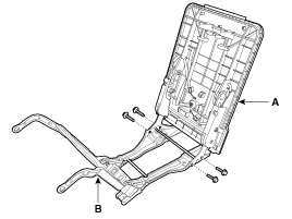
After loosening the mounting bolts, then disconnect the rear seat back
frame assembly (A) and rear seat cushion frame assembly (B).
|
Tightening torque :
44.1 ~ 53.9 N.m (4.5 ~ 5.5 kgf.m, 32.5 ~ 39.8 lb-ft)
|
|
| 4. |
Install in the reverse order of removal.
| •
|
Replace any damaged clips.
|
|
|
Component Location
[Second row seat assembly]
(Except Europe and Australia)
[5-seat vehicle]
1. Rear seat back frame assembly
[ ...
Other information:
On-vehicle Inpection
•
First of all, check for DTCs. If a DTC is present, perform troubleshooting
in accordance with the procedure for that DTC. (Refer to DTC
guide)
...
The following maintenance services must be performed to ensure good emission
control and performance. Keep receipts for all vehicle emission services to protect
your warranty. Where both mileage and time are shown, the frequency of service is
deter mined by whichever occurs first.
I : Inspect ...
 Rear Seat Frame Assembly Components and components location
 Front Seat Belt


