Kia Carens: Air conditioning System / Ambient Temperature Sensor Repair procedures
Kia Carens RP (2013-2018) Service Manual / Heating,Ventilation And Air Conditioning / Air conditioning System / Ambient Temperature Sensor Repair procedures
| Inspection |
| 1. |
Turn the ignition switch OFF.
|
| 2. |
Remove the front bumper.
(Refer to Body - "Front Bumper Cover")
|
| 3. |
Disconnect ambient temperature sensor.
|
| 4. |
Check the resistance of the ambient temperature sensor between terminals
1 and 2 whether it changes by changing the ambient temperature.
Specification
|
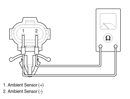
| 5. |
If the measured resistance is not within specification, substitute with
a known-good ambient temperature sensor and check for proper operation.
|
| 6. |
Replace the ambient temperature sensor if it is proved that there is
a problem with the sensor.
|
| Replacement |
| 1. |
Disconnect the negative (-) battery terminal.
|
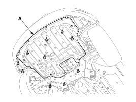
| 2. |
Remove the engine room under cover (A) by loosening the mounting clips
and bolts.
|
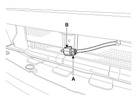
| 3. |
Disconnect the connector (A) and then remove the ambient temperature
sensor (B).
|
| 4. |
Install in the reverse order of removal.
|
 Ambient Temperature Sensor Description and operation
Description
The ambient temperature sensor is located at the front of the condenser and
detects ambient air temperature. It is a negative type thermistor; resistance
will increas ...
 Auto Defogging Sensor (DATC only) Description and operation
Description
The auto defogging sensor is installed on the front window glass. The sensor
judges and sends signal if moisture occurs to blow out wind for defogging. The
air condit ...
Other information:
Kia Carens RP (2013-2018) Owners Manual: Good braking practices
WARNING Whenever you leave or park your vehicle, always set the parking brake as far as possible and fully engage the vehicle's transaxle into the P (Park) position. If the parking brake is not fully engaged, the vehicle may move inadvertently and injure yourself and others. All vehicles sh ...
Kia Carens RP (2013-2018) Owners Manual: Side air bag
Your vehicle is equipped with a side air bag in each front seat. The purpose of the air bag is to provide the vehicle's driver and/or the front passenger with additional protection than that offered by the seat belt alone. The side air bags are designed to deploy only during certain sideimpact col ...
Copyright © www.kicaman.com 2015-2026
