Kia Carens: ABS(Anti-Lock Brake System) / Schematic diagrams
Kia Carens RP (2013-2018) Service Manual / Brake System / ABS(Anti-Lock Brake System) / Schematic diagrams
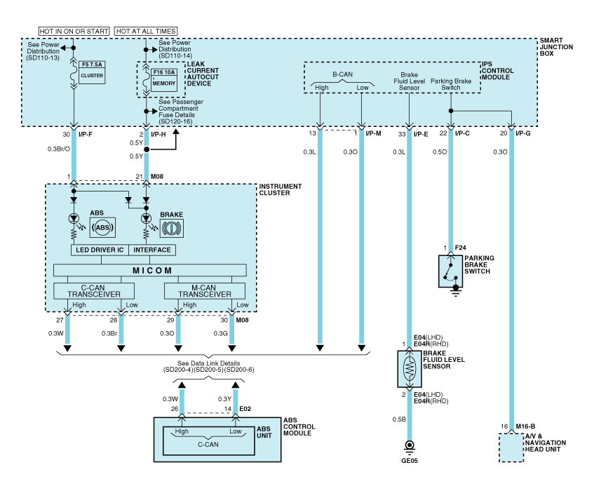
| Circuit Diagram - ABS (1) |

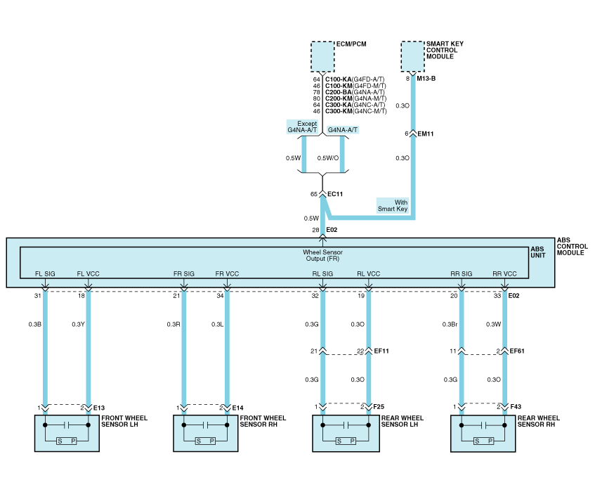
| Circuit Diagram - ABS (2) |

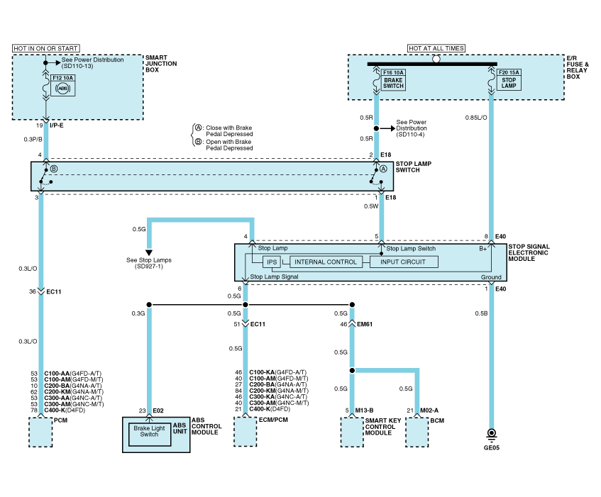
| Circuit Diagram - ABS (3) |

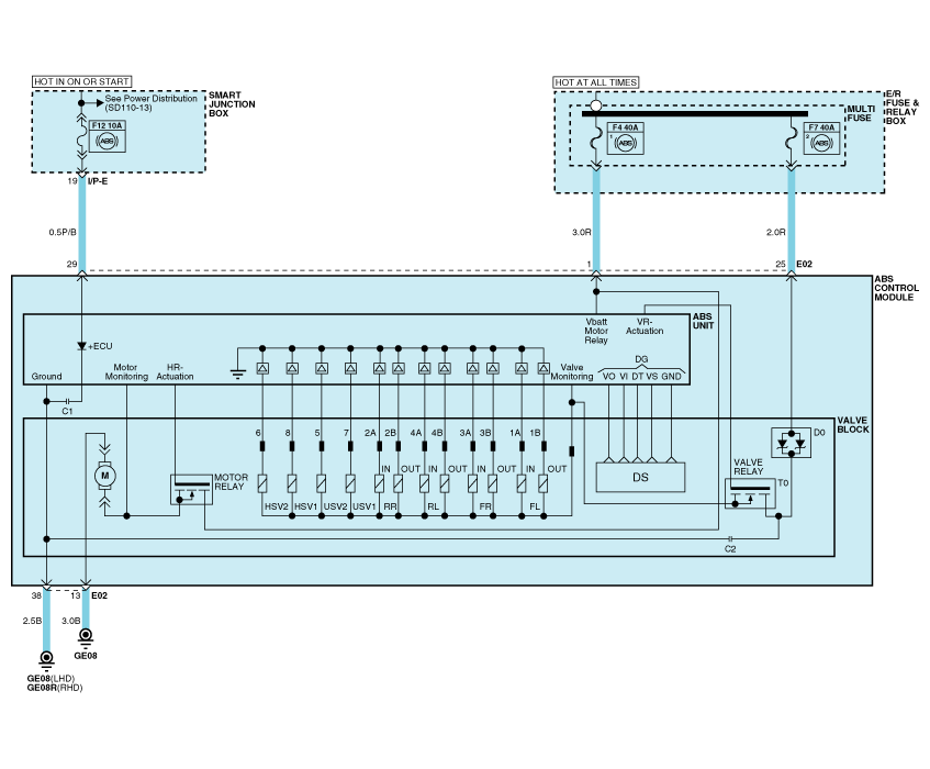
| Circuit Diagram - ABS (4) |

| ABS connector input/output |

|
Connector Terminal |
Specification |
|
|
No |
Description |
|
|
29 |
IGNITION1(+) |
High level of wake up voltage : 4.5V < V < 16.0V Low level of wake up voltage : V < 2.4V Max. current : I < 50mA |
|
25 |
POS. BATTERY 1.(SOLENOID) |
Over voltage range : 17.0 ± 0.5V Operating voltage range : 10.0 ± 0.5V < V < 16.0 ± 0.5V Low voltage range : 7.0 ± 0.5V < V < 9.5 ± 0.5V Max. current : I < 25A Max. leakage current : I < 0.25mA |
|
1 |
POS. BATTERY 2.(MOTOR) |
Operating voltage range: 10.0 ± 0.5V < V < 16.0 ± 0.5V Rush current : I < 110A Max current : I < 40A Max leakage current : I < 0.25mA |
|
38 |
GROUND |
Rated current : I <550mA Max. current: I < 25A |
|
13 |
PUMP MOTOR GROUND |
Rush current : I < 110A Max current : I < 40A |
|
23 |
BRAKE LIGHT SWITCH |
Input voltage (Low) : V < 2V Input voltage (High) : V > 6V Max. Input current : I < 3mA (@12.8V) |
|
28 |
SENSOR FRONT RIGHT OUTPUT |
External pull up resistance :1 KΩ < R Output duty :50 ± 20% |
|
14 |
CAN BUS LINE(LOW) |
Max. Input current : I < 10mA |
|
26 |
CAN BUS LINE(HIGH) |
|
|
18 |
SENSOR FRONT LEFT POWER |
Output voltage : V_BAT1 -0.6V ~ V_BAT1 -1.1V Output current : Max 30mA |
|
34 |
SENSOR FRONT RIGHT POWER |
|
|
19 |
SENSOR REAR LEFT POWER |
|
|
33 |
SENSOR REAR RIGHT POWER |
|
|
31 |
SENSOR FRONT LEFT SIGNAL |
Input current LOW : 5.9 ~ 8.4mA Input current HIGH :11.8 ~ 16.8mA Frequency range :1 ~ 2500Hz Input duty : 50 ± 10% |
|
21 |
SENSOR FRONT RIGHT SIGNAL |
|
|
32 |
SENSOR REAR LEFT SIGNAL |
|
|
20 |
SENSOR REAR RIGHT SIGNAL |
|
 Description and operation
Description
This specification applies to HCU(Hydraulic Control Unit) and ECU(Electronic
Control Unit) of the HECU.(Hydraulic and Electronic Control Unit)
This specification is ...
 Troubleshooting
Standard Flow of Diagnostic Troubleshooting
Notes With Regard To Diagnosis
The phenomena listed in the following table are not abnormal.
Condition
Explanat ...
Other information:
Kia Carens RP (2013-2018) Service Manual: EBD(Electronic Brake-force Distribution) Description and operation
Description The EBD system (Electronic Brake force Distribution) as a sub-system of the ABS system is to control the effective adhesion utilization by the rear wheels. It further utilizes the efficiency of highly developed ABS equipment by controlling the slip of the ...
Kia Carens RP (2013-2018) Service Manual: Components and components location
Components 1. Clutch release fork 2. Clutch cover assembly 3. Clutch disk assembly 4. Clutch release bearing ...
Copyright © www.kicaman.com 2015-2026

