Kia Carens: Manual Transaxle / Repair procedures
Kia Carens RP (2013-2018) Service Manual / Manual Transaxle System / Manual Transaxle / Repair procedures
| Removal |
| 1. |
Remove the air cleaner assembly and air duct.
(Refer to Engine Mechanical System - "Air Cleaner")
|
| 2. |
Remove the battery and battery tray.
(Refer to Engine Electrical System -"Battery")
|
| 3. |
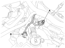
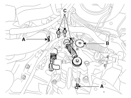
Disconnect the speed sensor connector (A) and back up lamp switch (B).
|
| 4. |
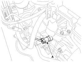
Disconnect the neutral switch connector (A).
|
| 5. |
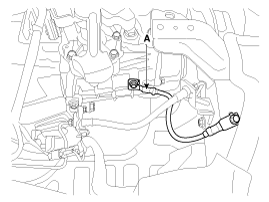
Remove the ground (A).
|
| 6. |
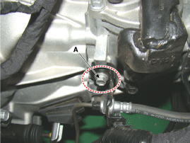
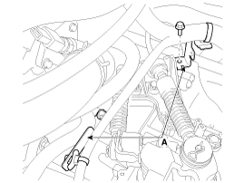
Remove the clutch tube bracket bolt (A).
|
| 7. |
Remove the wiring bracket (A).
|
| 8. |
Remove the control cable.
|
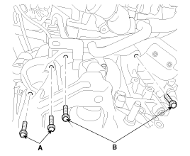
| 9. |
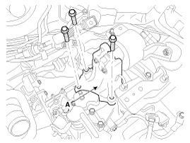
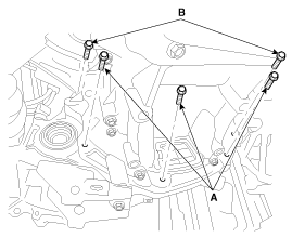
Remove the transaxle upper mounting bolt (B-2ea) and the starter mounting
bolt (A-2ea).
|
| 10. |
Remove the front wiper motor.
(Refer to Body Electrical System - "Front Wiper Motor")
|
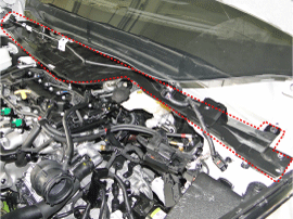
| 11. |
Remove the cowl top panel.
|
| 12. |
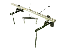
Assemble the engine support fixture (A).
(Refer to Special Service Tools - "Engine support fixture assembly drawing")
|
| 13. |
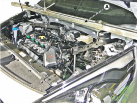
Using the engine support fixture (A), hold the engine and transaxle
assembly safely.
|
| 14. |
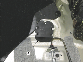
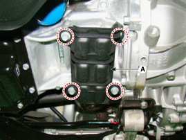
Remove the cover (A).
|
| 15. |
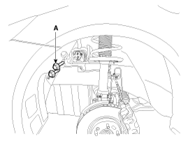
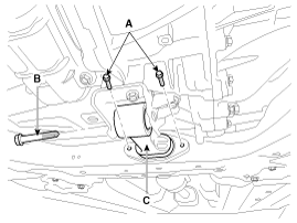
Remove the transaxle mounting bracket bolts (A).
|
| 16. |
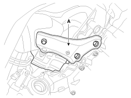
Remove the transaxle support bracket (A).
|
| 17. |
Remove the under cover and side cover.
(Refer to Engine Mechanical System - "Engine Room Under Cover")
|
| 18. |
Remove the drive shaft assembly.
(Refer to Driveshaft and axle - "Front Driveshaft")
|
| 19. |
Remove the heat protector (A).
|
| 20. |
Remove the air guide (A).
|
| 21. |
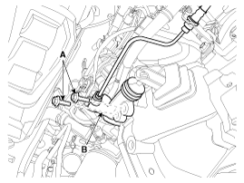
Remove the clutch release cylinder assembly (B) after removing the bolts
(A).
|
| 22. |
Remove the roll rod bracket (C) after removing bolt (A,B).
|
| 23. |
Remove the mounting bolt (A, B) after supporting the transaxle by a
jack.
|
| 24. |
Remove the transaxle while slowly lower the jack.
|
| Installation |
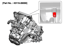
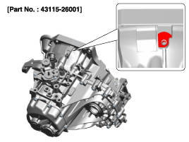
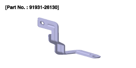
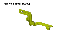
When replacing a clutch housing or transaxle assembly, the wiring bracket
should be installed in accordance with the clutch housing type.
|
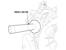
If the oil seal on the transaxle case side is damaged and fluid is leaking,
replace the oil seal with a new unit. When installing the new oil seal,
use the specialized tool (oil seal installer, 09431-26100).
|
| 1. |
Install in the reverse order of removal.
|
| 2. |
Adding manual transaxle fluid after Installing the manual transaxle.
(Refer to Manual Transaxle System - "Manual Transaxle Fluid")
|
 Components and components location
Components Location
1. Manual transaxle assembly
Components
1. Control shaft complete
2. Back-up lamp switch
3. Co ...
Other information:
Kia Carens RP (2013-2018) Service Manual: Front Door Module Components and components location
Component Location 1. Front door module ...
Kia Carens RP (2013-2018) Service Manual: Torque Converter Control Solenoid Valve (T/CON_VFS) Description and operation
Description • Torque converter control solenoid valve is a Variable Force Solenoid (VFS) type. • When TCM supplies variable current to solenoid valve, hydraulic pressure of torque converter clutch is controlled by solenoid ...
Copyright © www.kicaman.com 2015-2026


